Tag Archives: mounting gearbox

China Coaxial Output Cycloidal Gearbox with Foot Mounting cycloidal drive dimensions

Solution Description

Starshine Generate Cycloid Geared Motor Characteristics

1. Functions:
1. Sleek operating,lower noise equipment tooth needle far more engagement.
two. Cycloidal tooth profile offers a high get in touch with ratio to stand up to overload shocks
three. Compact dimensions: one ratio available from 1/9 to 1/87, double phase up from 1/ninety nine to 1/7569 
4. Perfect for dynamic apps: repeated start off-stop-reversing obligations suits for cyclo pace reducer because inertia is lower
5. Minimize maintenance expenses: substantial dependability, lengthy daily life, minimal servicing in comparison to typical gearboxes
six. Interior elements replaceable with other manufacturers to make sure operating.

7. Grease Lubricated & Oil Lubricated Versions Available
eight. Output Shaft Rotation Route: Solitary Reduction: Clockwise Rotation Double Reduction→ Counter Clockwise Rotation
9. Ambient Conditions: Indoor Set up:10-40 Celsius, Max eighty five% Humidity, Underneath 1000m Altitude, Nicely Ventilated Setting, Free of corrosive,        explosive gases, vapors and dust
10.Sluggish Velocity Shaft Route: Horizontal, Vertical Up & Down, Common Path
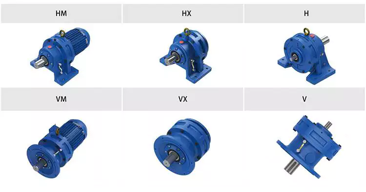
11.Mounting Style: Foot Mount, Flange Mount & Vertical F-flange Mount,
12. Input Relationship: Cyclo Integral Motor, Hollow Input Shaft Adapter
thirteen. Coupling Approach With Pushed Equipment: Coupling, Gears, Chain Sprocket Or Belt
fourteen. Cycloid reducer Capacity Assortment: .37kW ~ 11kW

two. Specialized parameters

Sort Aged Type Output Torque Output Shaft Dia.
SXJ00 JXJ00 98N.m φ30
SXJ01 JXJ01 221N.m φ35
SXJ02 JXJ02 448N.m φ45
SXJ03 JXJ03 986N.m φ55
SXJ04 JXJ04 1504N.m φ70
SXJ05 JXJ05 3051N.m φ90
SXJ06 JXJ06 5608N.m φ100

About Us

ZheJiang CZPT Travel Co.,Ltd,the predecessor was a state-owned  mould company, was recognized in 1965. CZPT specializes in the complete electrical power transmission solution for high-finish products producing industries dependent on the intention of “System Solution, Software Design and Skilled Provider”.
Starshine have a strong technical pressure with above 350 personnel at existing, including above thirty engineering technicians, thirty good quality inspectors, covering an region of 80000 square CZPT and types of advanced processing machines and screening equipments. We have a good foundation for the sector application advancement and service of higher-stop pace reducers & variators proudly owning to the provincial engineering technologies analysis center,the lab of gear pace reducers, and the base of modern day R&D.

Our Staff

Quality Management
Good quality:Insist on Advancement,Attempt for CZPT With the development of equipment producing indurstry,consumer by no means satirsfy with the present high quality of our items,on the opposite,wcreate the worth of high quality.
Good quality coverage:to boost the general amount in the discipline of electrical power transmission  
Top quality Look at:Constant Improvement , pursuit of excellence
Good quality Philosophy:Quality produces benefit

3. Incoming Top quality Handle
To build the AQL satisfactory degree of incoming materials manage, to give the material for the complete inspection, sampling, immunity. On the acceptance of qualified goods to warehousing, substandard goods to consider return, check out, rework, rework inspection dependable for monitoring negative, to monitor the supplier to consider corrective 
steps to avoid recurrence.

four. Process Quality Handle
The production internet site of the first evaluation, inspection and ultimate inspection, sampling in accordance to the requirements of some assignments, judging the good quality alter pattern
 found abnormal phenomenon of producing, and supervise the manufacturing division to enhance, eradicate the abnormal phenomenon or state.

five. FQC(Final QC)
Following the manufacturing department will comprehensive the merchandise, stand in the customer’s situation on the concluded merchandise good quality verification, in buy to ensure the quality of 
customer expectations and wants.

6. OQC(Outgoing QC)
After the merchandise sample inspection to decide the certified, permitting storage, but when the completed merchandise from the warehouse prior to the formal shipping of the items, there is a check, this is referred to as the cargo inspection.Check content:In the warehouse storage and transfer standing to validate, while confirming the shipping of the 
solution is a product inspection to decide the competent goods.

7. Certification.

Packing

Shipping


/ Piece
|
1 Piece

(Min. Order)

###

Application: Motor, Machinery, Agricultural Machinery
Hardness: Hardened Tooth Surface
Installation: Horizontal Type
Layout: Coaxial
Gear Shape: Cycloidal Pin
Step: Single-Step

###

Customization:
Available

|


###

Type Old Type Output Torque Output Shaft Dia.
SXJ00 JXJ00 98N.m φ30
SXJ01 JXJ01 221N.m φ35
SXJ02 JXJ02 448N.m φ45
SXJ03 JXJ03 986N.m φ55
SXJ04 JXJ04 1504N.m φ70
SXJ05 JXJ05 3051N.m φ90
SXJ06 JXJ06 5608N.m φ100

How to Use a Cyclone Gearbox

Often, a cycloidal gearbox is used in order to achieve a torque transfer from a motor or pump. This type of gearbox is often a common choice as it has a number of advantages over a regular gearbox. Its main advantage is that it is easy to make, which means that it can be incorporated into a variety of applications. However, if you want to use a cycloidal gearbox, there are a few things that you need to know. These include the operation principle, the structure and the dynamic and inertial effects that come with it.helical gearbox
Dynamic and inertial effects

Several studies have been carried out on the static and dynamic properties of cycloidal gears. The study of these effects is beneficial in assisting optimal design of cycloidal speed reducers.
In this paper, the dynamic and inertial effects of a two-stage cycloidal speed reducer have been investigated using the CZPT program package. Moreover, a new model for cycloidal reducers based on non-linear contact dynamics has been developed. The new model aims to predict several operational conditions.
The normal excitation contact force for the cycloid discs of the first and second stage is very similar. However, the total deformation at the contact point is different. This effect is mainly due to the system’s own oscillations. The cycloid discs of the second stage turn around the ring gear roller with a 180deg angle. This angle is a significant contributor to the torque loads. The total excitation force on the cycloid discs of first and second stage is 1848 N and 2068.7 N, respectively.
In order to analyze the contact stress, different gear profiles were investigated. The mesh density was considered as an important design criterion. It was found that a bigger hole reduces the material content of the cycloidal disc and results in more stresses.
Moreover, it is possible to reduce the contact forces in a more efficient manner by changing the geometric parameters. This can be done by mesh refinement along the disc width. The cycloidal disc has the greatest influence on the output results.
The efficiency of a cycloidal drive increases with the increase in load. The efficiency of a cycloidal reducer also depends on the eccentricity of the input shaft and the cycloidal plate. The efficiency curve for small loads is linear. However, for the larger loads, the efficiency curve becomes more non-linear. This is because the stiffness of the cycloid reducer increases as the load increases.

Structure

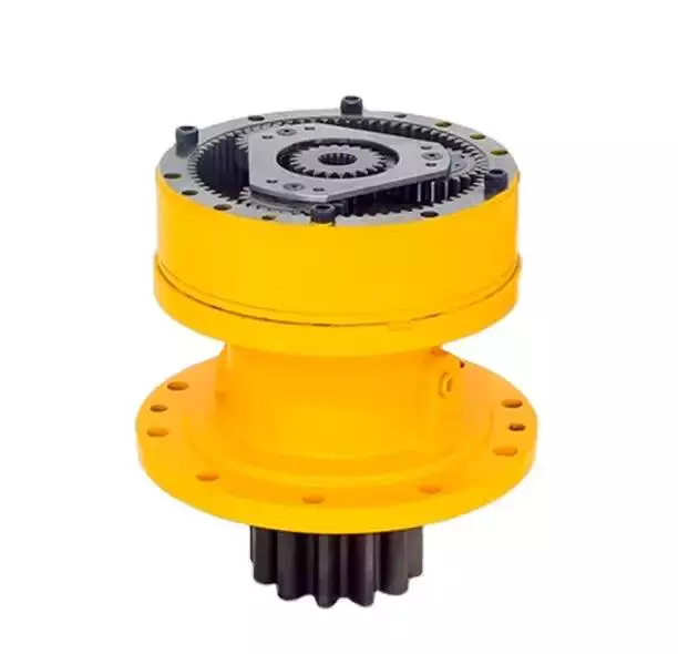
Despite the fact that it looks like a complicated engineering puzzle, the construction of a cycloidal gearbox is actually quite simple. The key elements are the base, the load plate and the thrust bearing. All these elements work together to create a stable, compact gearbox.
The base is a circular section with several cylindrical pins around its outer edge. The pins are fixed on a fixed ring that holds them in a circular path. The ring serves as a reference circle. The circle’s size is approximately 5mm in diameter.
The load plate is a series of threaded screw holes. These are arranged 15mm away from the center. These are used to anchor external structures. The load plate must be rotated around the X and Y axis.
The thrust bearing is placed on top of the load plate. The bearing is made of an internal diameter of 35mm and an external diameter of 52mm. It is used to allow rotation around the Z axis.
The cycloidal disc is the centerpiece of the cycloidal gearbox. The disc has holes for the pins that drive the output shaft. The holes are larger than those used in output roller pins. The disc also has a reduced eccentricity.
The pins are attached to the cycloidal disc by rolling pins. The pins are made of a material that provides mechanical support for the drive during high-torque situations. The pins have a 9mm external diameter. The disc has a number of lobes and is rotated by one lobe per shaft revolution.
The cycloidal gearbox also has a top cover that helps keep the components together. The cover has a pocket for tools. The top cover also has threads that screw into the casing.helical gearbox
Operation principle

Among many types of gear transmissions, cycloidal gearboxes are used in heavy machinery and multi-axis robots. They are highly effective, compact and capable of high ratios. In addition, they have an overload capability.
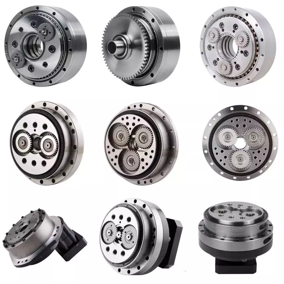
Cycloid disks are driven by eccentric shafts that rotate around fixed ring pins. Roller pins of the pin disc engage with holes in the cycloidal disc. These roller pins drive the pin disc and the pin disc transfers the motion to the output shaft.
Unlike conventional gear drives, cycloidal drives have low backlash and high torsional stiffness. They are ideally suited to heavy loads and all drive technologies. The lower mass and compact design of the cycloidal disk also contributes to its high efficiency and positioning accuracy.
The cycloidal disc plays a central role in the gearbox kinematics. It rotates around a fixed ring in a circle. When the disc is pushed against the ring gear, the pins engage with the disc and the roller pins rotate around the pins. This rotating motion generates vibration, which travels through the driven shafts.
Cycloid discs are typically designed with a short cycloid, so that the eccentricity is minimized. This reduces unbalance forces at high speeds. Ideally, the number of lobes on the cycloid is smaller than the number of surrounding pins. This reduces the amount of Hertzian contact stress.
Unlike planetary gears, cycloidal gears have high accuracy and are capable of withstanding shock loads. They also experience low friction and less wear on tooth flanks. They also have higher efficiency and load capacity.
Cycloid gears are generally more difficult to manufacture than involute gears. Cycloid gears are not suitable for stacking gear stages. They require extreme accuracy for manufacturing. However, their smaller size and low backlash, high torsional stiffness, and low vibration make them ideal for use in heavy machines.

Involute gear tooth profile

Almost all gears are manufactured with an involute gear tooth profile. Cycloid gears are also produced with this profile. Compared with involute gears, cycloid gears are stronger and can transmit more power. However, they can also be more difficult to manufacture. This makes them costlier.
The involute gear tooth profile is a smooth curve. It is derived from the involute curve of a circle. A tangent to the base circle is the normal at any point of an involute.
This curve has properties that allow the involute gear teeth to transfer motion in perpendicular direction. It is also the path traced by the end of the string unwrapping from a cylinder.
An involute profile has the advantage of being easy to manufacture. It also allows for smooth meshing despite misalignment of the centre distance. This profile is also preferred over a cycloid tooth profile, but it is not the best in every regard.
Cycloid gear teeth are also made of two curves. Unlike involute teeth, cycloid gear teeth have a consistent radius. Cycloid gears are less likely to produce noise. But they are also more expensive to manufacture.
Involute teeth are easier to manufacture because they have only one curve. Cycloid gears can also be made with a rack type cutter. This makes them cheaper to manufacture. However, they require an expert design. They can also be manufactured with a gear shaper that includes a pinion cutter.
The tooth profiles that satisfy the law of gear-tooth action are sometimes called conjugate profiles. The involute profile is the most common of these. It allows for constant torque transmission.helical gearbox
Backlash

Typically, cycloidal drives provide a high ratio of transmission with no backlash. This is because the cycloid disc is driven by an eccentric shaft. During rotation, the cycloid disc rotates around a fixed ring. This ring also rotates independently of the center of gravity.
The cycloid disc is typically shortened to reduce the eccentricity. This helps to minimize the unbalance forces that may occur at high speeds. The cycloid also offers a larger gear ratio than traditional gears. This provides a better positional accuracy.
Cycloid drives also have a high torsional stiffness. This provides greater torsional resilience and shock load capabilities. This is important for a number of reasons, such as in heavy-duty applications.
Cycloid drives also have lower mass. These benefits make them ideally suited for all drive technologies. The design also allows for higher torsional stiffness and service life. These drives also have a much smaller profile.
Cycloid drives are also used to reduce speed. Because of the high torsional stiffness of the cycloid, they also have high positioning accuracy.
Cycloid drives are well-suited to a variety of applications, including electric motors, generators, and pump motors. They are also highly resistant to shock loads, which is important in a variety of applications. This design is ideal for applications that require a large transmission ratio in a compact design.
Cycloid drives also have the advantage of minimizing the clearance between the mating components. This helps to eliminate interference and ensure a positive fit. This is particularly important in gearboxes. It also allows for the use of a load cell and potentiometer to determine the backlash of the gearbox.
China Coaxial Output Cycloidal Gearbox with Foot Mounting     cycloidal drive dimensionsChina Coaxial Output Cycloidal Gearbox with Foot Mounting     cycloidal drive dimensions
editor by CX 2023-03-27

China Suit Impact and Loading Situations Cycloidal Gearbox with Foot Mounting for Impact and Loading Situations cycloidal gear drive

Item Description

Starshine Drive Cycloid Geared Motor Characteristics

1. Functions:
one. Smooth working,lower sounds gear tooth needle a lot more engagement.
2. Cycloidal tooth profile supplies a higher make contact with ratio to endure overload shocks
3. Compact size: one ratio obtainable from 1/9 to 1/87, double stage up from 1/99 to 1/7569 
four. Excellent for dynamic applications: regular start off-cease-reversing duties fits for cyclo pace reducer given that inertia is reduced
5. Minimize maintenance expenses: high dependability, extended existence, minimal maintenance in comparison to typical gearboxes
6. Internal areas replaceable with other manufacturers to guarantee running.

7. Grease Lubricated & Oil Lubricated Versions Available
eight. Output Shaft Rotation Direction: Single Reduction: Clockwise Rotation Double Reduction→ Counter Clockwise Rotation
9. Ambient Situations: Indoor Set up:10-forty Celsius, Max 85% Humidity, Underneath 1000m Altitude, Well Ventilated Environment, Free of corrosive,        explosive gases, vapors and dust
10.Gradual Pace Shaft Route: Horizontal, Vertical Up & Down, Universal Route
11.Mounting Style: Foot Mount, Flange Mount & Vertical F-flange Mount,
twelve. Input Link: Cyclo Integral Motor, Hollow Enter Shaft Adapter
thirteen. Coupling Method With Driven Equipment: Coupling, Gears, Chain Sprocket Or Belt
14. Cycloid reducer Capability Variety: .37kW ~ 11kW

two. Technological parameters

Sort Aged Variety Output Torque Output Shaft Dia.
SXJ00 JXJ00 98N.m φ30
SXJ01 JXJ01 221N.m φ35
SXJ02 JXJ02 448N.m φ45
SXJ03 JXJ03 986N.m φ55
SXJ04 JXJ04 1504N.m φ70
SXJ05 JXJ05 3051N.m φ90
SXJ06 JXJ06 5608N.m φ100

About Us

ZheJiang CZPT Co.,Ltd,the predecessor was a state-owned military CZPT business, was established in 1965. CZPT specializes in the total energy transmission resolution for substantial-finish equipment producing industries based on the aim of “System Item, Software Style and Professional Service”.
Starshine have a sturdy complex force with above 350 staff at current, which includes above thirty engineering professionals, thirty good quality inspectors, covering an location of 80000 square meters and kinds of innovative processing equipment and testing equipments. We have a good foundation for the market software advancement and provider of higher-end velocity reducers & variators owning to the provincial engineering technological innovation study heart,the lab of gear velocity reducers, and the foundation of modern R&D.

Our Team

Top quality Manage
Top quality:Insist on Improvement,Strive for Excellence With the development of equipment manufacturing indurstry,customer never satirsfy with the current quality of our products,on the contrary,wcreate the value of quality.
Quality policy:to enhance the overall level in the field of power transmission  
Quality View:Continuous Improvement , pursuit of excellence
Quality Philosophy:Quality creates value

three. Incoming Quality Control
To establish the AQL acceptable level of incoming material control, to provide the material for the whole inspection, sampling, immunity. On the acceptance of qualified products to warehousing, substandard goods to take return, check, rework, rework inspection responsible for tracking bad, to monitor the supplier to take corrective 
measures to prevent recurrence.

four. Process Quality Control
The manufacturing site of the first examination, inspection and final inspection, sampling according to the requirements of some projects, judging the quality change trend
 found abnormal phenomenon of manufacturing, and supervise the production department to improve, eliminate the abnormal phenomenon or state.

5. FQC(Final QC)
After the manufacturing department will complete the product, stand in the customer’s position on the finished product quality verification, in order to ensure the quality of 
customer expectations and needs.

six. OQC(Outgoing QC)
After the product sample inspection to determine the qualified, allowing storage, but when the finished product from the warehouse before the formal delivery of the goods, there is a check, this is called the shipment inspection.Check content:In the warehouse storage and transfer status to confirm, while confirming the delivery of the 
merchandise is a product inspection to determine the qualified products.

7. Certification.

Packing

Supply


US $50-220
/ Piece
|
2 Pieces

(Min. Order)

###

Application: Motor, Machinery, Agricultural Machinery, Machine and Conveyor
Hardness: Hardened Tooth Surface
Installation: Horizontal Type
Layout: Coaxial
Gear Shape: Coaxial
Step: Single-Step

###

Samples:
US$ 400/Piece
1 Piece(Min.Order)

|
Request Sample

###

Customization:

###

Type Old Type Output Torque Output Shaft Dia.
SXJ00 JXJ00 98N.m φ30
SXJ01 JXJ01 221N.m φ35
SXJ02 JXJ02 448N.m φ45
SXJ03 JXJ03 986N.m φ55
SXJ04 JXJ04 1504N.m φ70
SXJ05 JXJ05 3051N.m φ90
SXJ06 JXJ06 5608N.m φ100

A Mathematical Model of a Cycloid Gearbox

Having a gearbox with a cycloidal rotor is an ideal design for a car or any other vehicle, as the cycloidal design can reduce the amplitude of vibration, which is a key component in car performance. Using a cycloidal gearbox is also a great way to reduce the amount of friction between the gears in the gearbox, which can help to reduce noise and wear and tear. A cycloidal gearbox is also a very efficient design for a vehicle that needs to perform under high loads, as the gearbox can be very robust against shock loads.helical gearbox

Basic design principles

cycloidal gearboxes are used for precision gearing applications. Cycloidal drives are compact and robust and offer lower backlash, torsional stiffness and a longer service life. They are also suitable for applications involving heavy loads.
Cycloidal drives are compact in size and provide very high reduction ratios. They are also very robust and can handle shock loads. Cycloidal drives are ideally suited to a wide range of drive technologies. Cycloidal gears have excellent torsional stiffness and can provide a transmission ratio of 300:1. They can also be used in applications where stacking multiple gear stages is not desired.
In order to achieve a high reduction ratio, cycloidal gears must be manufactured extremely accurately. Cycloidal gears have a curved tooth profile that removes shear forces at any point of contact. This provides a positive fit for the gear disc. This profile can be provided on a separate outer bushing or as an internal gear profile insert.
Cycloidal drives are used in marine propulsion systems, where the load plate rotates around the X and Y axis. The plate is anchored by a threaded screw hole arranged 15mm away from the center.
A secondary carrier body is used in a cycloidal gearbox to support the load plate. The secondary carrier body is composed of a mounting carrier body and a secondary carrier disc.

Low friction

Several studies have been conducted to understand the static problems of gears. In this paper, we discuss a mathematical model of a low friction cycloidal gearbox. This model is designed to calculate various parameters that affect the performance of the gearbox during production.
The model is based on a new approach that includes the stiction effect and the nonlinear friction characteristic. These parameters are not covered by the conventional rule of thumb.
The stiction effect is present when the speed direction is changed. During this time, the input torque is required to prevail over the stiction effect to generate movement. The model also enables us to calculate the magnitude of the stiction effect and its breakaway speed.
The most important thing is that the model can be used to improve the dynamic behavior of a controlled system. In this regard, the model has a high degree of accuracy. The model is tested in several quadrants of the gearbox to find the optimum stiction breakaway speed. The simulation results of the model show that this model is effective in predicting the efficiency of a low friction cycloidal gearbox.
In addition to the stiction model, we also studied the efficiency of a low friction cycloidal reducer. The reduction ratio of this gearbox was estimated from the formula. It is found that the ratio approaches negative infinity when the motor torque is close to zero Nm.

Compact

Unlike standard planetary gears, cycloidal gearboxes are compact, low friction and feature virtually zero backlash. They also offer high reduction ratios, high load capacity and high efficiency. These features make them a viable option for a variety of applications.
Cycloid disks are driven by an eccentric input shaft. They are then driven by a stationary ring gear. The ring gear rotates the cycloidal disk at a higher rate. The input shaft rotates nine times to complete a full rotation. The ring gear is designed to correct the dynamic imbalance.
CZPT cycloidal gearheads are designed for precision and stable operation. These reducers are robust and can handle large translocations. They also offer high overload protection. They are suitable for shock wave therapy. CZPT gearheads are also well suited for applications with critical positioning accuracy. They also require low assembly and design costs. They are designed for long service life and low hysteresis loss.
CZPT cycloidal reducers are used in a variety of industrial applications, including CNC machining centers, robot positioners and manipulators. They offer a unique design that can handle high forces on the output axis, and are especially suitable for large translocations. These gearheads are highly efficient, reducing costs, and are available in a variety of sizes. They are ideal for applications that require millimetre accuracy.

High reduction ratios

Compared to other gearboxes, cycloidal gearboxes offer high reduction ratios and small backlash. They are also less expensive. Cycloid gearboxes can be used in a variety of industries. They are suitable for robotic applications. They also have high efficiency and load capacity.
A cycloidal gearbox works by rotating a cycloidal disc. This disc contains holes that are bigger than the pins on the output shaft. When the disc is rotated, the output pins move in the holes to generate a steady output shaft rotation. This type of gearbox does not require stacking stages.
Cycloid gearboxes are usually shorter than planetary gearboxes. Moreover, they are more robust and can transmit higher torques.
Cycloid gearboxes have an eccentric cam that drives the cycloidal disc. The cycloidal disc advances in 360deg/pivot/roller steps. It also rotates in an eccentric pattern. It meshes with the ring-gear housing. It also engages the internal teeth of the ring-gear housing.
The number of lobes on the cycloidal disc is not sufficient to generate a good transmission ratio. In fact, the number of lobes must be less than the number of pins surrounding the cycloidal disc.
The cycloidal disc is rotated by an eccentric cam that extends from the base shaft. The cam also spins inside the cycloidal disc. The eccentric motion of the cam helps the cycloidal disc rotate around the pins of the ring-gear housing.helical gearbox

Reducing amplitude of the vibration

Various approaches to reducing amplitude of the vibration in a cycloidal gearbox have been studied. These approaches are based on the kinematic analysis of gearbox.
A cycloidal gearbox is a gearbox that consists of bearings, gears, and an eccentric bearing that drives a cycloidal disc. This gearbox has a high reduction ratio, which is achieved by a series of output shaft pins that drive the output shaft as the disc rotates.
The test bench used in the studies has four sensors. Each sensor acquires signals with different signal processing techniques. In addition, there is a tachometer that acquires variations in rotational velocity at the input side.
The kinematic study of the robotic gearbox was performed to understand the frequency of vibrations and to determine whether the gearbox is faulty. It was found that the gearbox is in healthy operation when the amplitude of the x and y is low. However, when the amplitude is high, it is indicative of a malfunctioning element.
The frequency analysis of vibration signals is performed for both cyclostationary and noncyclostationary conditions. The frequencies that are selected are those that appear in both types of conditions.

Robust against shock loads

Compared to traditional gearboxes, cycloidal gearboxes have significant benefits when it comes to shock loads. These include high shock-load capacity, high efficiency, reduced cost, lower weight, lower friction, and better positioning accuracy.
Cycloid gears can be used to replace traditional planetary gears in applications where inertia is important, such as the transportation of heavy loads. They have a lighter design and can be manufactured to a more compact size, which helps reduce cost and installation expense. Cycloid gears are also able to provide transmission ratios of up to 300:1 in a small package.
Cycloid gears are also suitable for applications where a long service life is essential. Their radial clamping ring reduces inertia by up to 39%. Cycloid gears have a torsional stiffness that is five times higher than that of conventional planetary gears.
Cycloid gearboxes can provide significant improvements in concrete mixers. They are a highly efficient design, which allows for important innovations. They are also ideal for servo applications, machine tools, and medical technology. They feature user-friendly screw connections, effective corrosion protection, and effective handling.
Cycloid gears are especially useful for applications with critical positioning accuracy. For example, in the control of large parabolic antennas, high shock load capacity is required to maintain accuracy. Cycloid gears can withstand shock loads up to 500% of their rated torque.helical gearbox

Inertial effects

Various studies have been conducted to investigate the static problems of gears. However, there is still a need for a proper model to investigate the dynamic behaviour of a controlled system. For this, a mathematical model of a cycloidal gearbox has been developed. The presented model is a simple model that can be used as the basis for a more complex mechanical model.
The mathematical model is based on the cycloidal gearbox’s mechanical construction and has a nonlinear friction characteristic. The model is able to reproduce the current peaks and breaks at standstill. It also considers the stiction effect. However, it does not cover backlash or torsional stiffness.
This model is used to calculate the torque generating current and the inertia of the motor. These values are then compared with the real system measurement. The results show that the simulation results are very close to the real system measurement.
Several parameters are considered in the model to improve its dynamic behaviour. These parameters are calculated from the harmonic drive system analysis. These are torque-generating current, inertia, and the contact forces of the rotating parts.
The model has a high level of accuracy and can be used for motor control. It is also able to reproduce the dynamic behaviour of a controlled system.
China Suit Impact and Loading Situations Cycloidal Gearbox with Foot Mounting for Impact and Loading Situations     cycloidal gear driveChina Suit Impact and Loading Situations Cycloidal Gearbox with Foot Mounting for Impact and Loading Situations     cycloidal gear drive
editor by czh 2023-01-23

China Cycloidal Gearbox Horizontal Mounting Speed Reducer Gearbox supplier

Product Description

Product Description

Cycloidal Gearbox Horizontal Mounting speed Reducer gearbox

Components:

1. Housing: Cast Iron
2. Gearset: Cycloid Wheel & Pin Wheel
3. Input Configurations:
Equipped with Electric Motors (AC Motor, Brake Motor, Explosion-proof Motor, Regulated Speed Motor, Hydraulic Motor)
IEC-normalized Motor Flange
Keyed Solid Shaft Input
4. Output Configurations:
Keyed Solid Shaft Output
 

Detailed Photos

Features:

1. Large reduction ratio, 1-stage ratio 9~87, 2-stage ratio 121~1849, larger reduction ratio is available by 3-stage or multistage combinations
2. High efficiency, the average efficiency is over 90%
3. Compact structure, light weight
4. Stable and reliable operation, low noise5. Long service life

Product Parameters

Parameters:

Models Power Ratio Max. Torque Output Shaft Dia. Input Shaft Dia.
1 Stage
X2(B0/B12) 0.37~1.5 9~87 150 Φ25(Φ30) Φ15
X3(B1/B15) 0.55~2.2 9~87 250 Φ35 Φ18
X4(B2/B18) 0.75~4.0 9~87 500 Φ45 Φ22
X5(B3/B22) 1.5~7.5 9~87 1,000 Φ55 Φ30
X6(B4/B27) 2.2~11 9~87 2,000 Φ65(Φ70) Φ35
X7 3.0~11 9~87 2,700 Φ80 Φ40
X8(B5/B33) 5.5~18.5 9~87 4,500 Φ90 Φ45
X9(B6/B39) 7.5~30 9~87 7,100 Φ100 Φ50

X10(B7/B45) 15~45 9~87 12,000 Φ110 Φ55
X11(B8/B55) 18.5~55 9~87 20,000 Φ130 Φ70
2 Stage
X32(B10) 0.25~0.55 121~1849 Φ35 Φ15
X42(B20/B1812) 0.37~0.75 121~1849 Φ45 Φ15
X53(B31/B2215) 0.55~1.5 121~1849 Φ55 Φ18
X63(B41/B2715) 0.75~2.2 121~1849 Φ65(Φ70) Φ18
X64(B42/B2718) 0.75~2.2 121~1849 Φ65(Φ70) Φ22
X74 1.1~3.0 121~1849 Φ80 Φ22
X84(B52/B3318) 1.5~4.0 121~1849 Φ90 Φ22
X85(B53/B3322) 2.2~5.5 121~1849 Φ90 Φ30
X95(B63/B3922) 3.0~7.5 121~1849 Φ100 Φ30
X106(B74/B4527) 4.0~11 121~1849 Φ110 Φ35
X117(B84/B5527) 4.0~15 121~1849 Φ130 Φ40(Φ35)

1 Stage Ratio: 9, 11, 17, 23, 29, 35, 43, 59, 71, 87
2 Stage Ratio: 121, 187, 289, 385, 473, 595, 731, 989, 1225, 1849

Installation:
Foot Mounted
Flange Mounted
Lubrication:

Foot-mounted Flange-mounted
1 Stage X2~X4 X5~X11 X2~X4 X5~X11
Grease Lubrication Oil-bath & Splash Lubrication Grease Lubrication Oil Pump Circulation Lubrication
2 Stage X32~X42 X53~X117 X32~X42 X53~X117
Grease Lubrication Oil-bath & Splash Lubrication Grease Lubrication Oil Pump Circulation Lubrication

Cooling:
Natural Cooling

Packaging & Shipping

Company Profile

Our Advantages

FAQ

1.Q:What kinds of gearbox can you produce for us?

A:Main products of our company: UDL series speed variator,RV series worm gear reducer, ATA series shaft mounted gearbox, X,B series gear reducer,
P series planetary gearbox and R, S, K, and F series helical-tooth reducer, more
than 1 hundred models and thousands of specifications
2.Q:Can you make as per custom drawing?
A: Yes, we offer customized service for customers.
3.Q:What is your terms of payment ?
A: 30% Advance payment by T/T after signing the contract.70% before delivery
4.Q:What is your MOQ?
A: 1 Set

Welcome to contact us for more detail information and inquiry.
If you have specific parameters and requirement for our gearbox, customization is available.

Application: Motor, Machinery, Agricultural Machinery, Industry
Function: Change Drive Torque, Change Drive Direction, Speed Changing, Speed Reduction, Speed Increase
Layout: Cycloidal
Hardness: Hardened
Installation: Vertical Type
Step: Double-Step

###

Samples:
US$ 50/Piece
1 Piece(Min.Order)

|
Request Sample

###

Customization:

###

Models Power Ratio Max. Torque Output Shaft Dia. Input Shaft Dia.
1 Stage
X2(B0/B12) 0.37~1.5 9~87 150 Φ25(Φ30) Φ15
X3(B1/B15) 0.55~2.2 9~87 250 Φ35 Φ18
X4(B2/B18) 0.75~4.0 9~87 500 Φ45 Φ22
X5(B3/B22) 1.5~7.5 9~87 1,000 Φ55 Φ30
X6(B4/B27) 2.2~11 9~87 2,000 Φ65(Φ70) Φ35
X7 3.0~11 9~87 2,700 Φ80 Φ40
X8(B5/B33) 5.5~18.5 9~87 4,500 Φ90 Φ45
X9(B6/B39) 7.5~30 9~87 7,100 Φ100 Φ50

###

X10(B7/B45) 15~45 9~87 12,000 Φ110 Φ55
X11(B8/B55) 18.5~55 9~87 20,000 Φ130 Φ70
2 Stage
X32(B10) 0.25~0.55 121~1849 Φ35 Φ15
X42(B20/B1812) 0.37~0.75 121~1849 Φ45 Φ15
X53(B31/B2215) 0.55~1.5 121~1849 Φ55 Φ18
X63(B41/B2715) 0.75~2.2 121~1849 Φ65(Φ70) Φ18
X64(B42/B2718) 0.75~2.2 121~1849 Φ65(Φ70) Φ22
X74 1.1~3.0 121~1849 Φ80 Φ22
X84(B52/B3318) 1.5~4.0 121~1849 Φ90 Φ22
X85(B53/B3322) 2.2~5.5 121~1849 Φ90 Φ30
X95(B63/B3922) 3.0~7.5 121~1849 Φ100 Φ30
X106(B74/B4527) 4.0~11 121~1849 Φ110 Φ35
X117(B84/B5527) 4.0~15 121~1849 Φ130 Φ40(Φ35)

###

Foot-mounted Flange-mounted
1 Stage X2~X4 X5~X11 X2~X4 X5~X11
Grease Lubrication Oil-bath & Splash Lubrication Grease Lubrication Oil Pump Circulation Lubrication
2 Stage X32~X42 X53~X117 X32~X42 X53~X117
Grease Lubrication Oil-bath & Splash Lubrication Grease Lubrication Oil Pump Circulation Lubrication

What Is a Gearbox?

There are several factors to consider when choosing a gearbox. Backlash, for example, is a consideration, as it is the angle at which the output shaft can rotate without the input shaft moving. While this isn’t necessary in applications without load reversals, it is important for precision applications involving load reversals. Examples of these applications include automation and robotics. If backlash is a concern, you may want to look at other factors, such as the number of teeth in each gear.
gearbox

Function of a gearbox

A gearbox is a mechanical unit that consists of a chain or set of gears. The gears are mounted on a shaft and are supported by rolling element bearings. These devices alter the speed or torque of the machine they are used in. Gearboxes can be used for a wide variety of applications. Here are some examples of how gearboxes function. Read on to discover more about the gears that make up a gearbox.
Regardless of the type of transmission, most gearboxes are equipped with a secondary gear and a primary one. While the gear ratios are the same for both the primary and secondary transmission, the gearboxes may differ in size and efficiency. High-performance racing cars typically employ a gearbox with two green and one blue gear. Gearboxes are often mounted in the front or rear of the engine.
The primary function of a gearbox is to transfer torque from one shaft to another. The ratio of the driving gear’s teeth to the receiving member determines how much torque is transmitted. A large gear ratio will cause the main shaft to revolve at a slower speed and have a high torque compared to its counter shaft. Conversely, a low gear ratio will allow the vehicle to turn at a lower speed and produce a lower torque.
A conventional gearbox has input and output gears. The countershaft is connected to a universal shaft. The input and output gears are arranged to match the speed and torque of each other. The gear ratio determines how fast a car can go and how much torque it can generate. Most conventional transmissions use four gear ratios, with one reverse gear. Some have two shafts and three inputs. However, if the gear ratios are high, the engine will experience a loss of torque.
In the study of gearbox performance, a large amount of data has been collected. A highly ambitious segmentation process has yielded nearly 20,000 feature vectors. These results are the most detailed and comprehensive of all the available data. This research has a dual curse – the first is the large volume of data collected for the purpose of characterization, while the second is the high dimensionality. The latter is a complication that arises when the experimental gearbox is not designed to perform well.
gearbox

Bzvacklash

The main function of a gearhead is to multiply a moment of force and create a mechanical advantage. However, backlash can cause a variety of issues for the system, including impaired positioning accuracy and lowered overall performance. A zero backlash gearbox can eliminate motion losses caused by backlash and improve overall system performance. Here are some common problems associated with backlash in gearheads and how to fix them. After you understand how to fix gearbox backlash, you’ll be able to design a machine that meets your requirements.
To reduce gearbox backlash, many designers try to decrease the center distance of the gears. This eliminates space for lubrication and promotes excessive tooth mesh, which leads to premature mesh failure. To minimize gearbox backlash, a gear manufacturer may separate the two parts of the gear and adjust the mesh center distance between them. To do this, rotate one gear with respect to the fixed gear, while adjusting the other gear’s effective tooth thickness.
Several manufacturing processes may introduce errors, and reducing tooth thickness will minimize this error. Gears with bevel teeth are a prime example of this. This type of gear features a small number of teeth in comparison to its mating gear. In addition to reducing tooth thickness, bevel gears also reduce backlash. While bevel gears have fewer teeth than their mating gear, all of their backlash allowance is applied to the larger gear.
A gear’s backlash can affect the efficiency of a gearbox. In an ideal gear, the backlash is zero. But if there is too much, backlash can cause damage to the gears and cause it to malfunction. Therefore, the goal of gearbox backlash is to minimize this problem. However, this may require the use of a micrometer. To determine how much gearbox backlash you need, you can use a dial gauge or feeler gauge.
If you’ve been looking for a way to reduce backlash, a gearbox’s backlash may be the answer. However, backlash is not a revolt against the manufacturer. It is an error in motion that occurs naturally in gear systems that change direction. If it is left unaccounted for, it can lead to major gear degradation and even compromise the entire system. In this article, we’ll explain how backlash affects gears and how it affects the performance of a gearbox.

Design

The design of gearboxes consists of a variety of factors, including the type of material used, power requirements, speed and reduction ratio, and the application for which the unit is intended. The process of designing a gearbox usually begins with a description of the machine or gearbox and its intended use. Other key parameters to consider during gearbox design include the size and weight of the gear, its overall gear ratio and number of reductions, as well as the lubrication methods used.
During the design process, the customer and supplier will participate in various design reviews. These include concept or initial design review, manufacturing design validation, critical design review, and final design review. The customer may also initiate the process by initiating a DFMEA. After receiving the initial design approval, the design will go through several iterations before the finalized design is frozen. In some cases, the customer will require a DFMEA of the gearbox.
The speed increaser gearboxes also require special design considerations. These gearboxes typically operate at high speeds, causing problems with gear dynamics. Furthermore, the high speeds of the unit increase frictional and drag forces. A proper design of this component should minimize the effect of these forces. To solve these problems, a gearbox should incorporate a brake system. In some cases, an external force may also increase frictional forces.
Various types of gear arrangements are used in gearboxes. The design of the teeth of the gears plays a significant role in defining the type of gear arrangement in the gearbox. Spur gear is an example of a gear arrangement, which has teeth that run parallel to the axis of rotation. These gears offer high gear ratios and are often used in multiple stages. So, it is possible to create a gearbox that meets the needs of your application.
The design of gearboxes is the most complex process in the engineering process. These complex devices are made of multiple types of gears and are mounted on shafts. They are supported by rolling element bearings and are used for a variety of applications. In general, a gearbox is used to reduce speed and torque and change direction. Gearboxes are commonly used in motor vehicles, but can also be found in pedal bicycles and fixed machines.
gearbox

Manufacturers

There are several major segments in the gearbox market, including industrial, mining, and automotive. Gearbox manufacturers are required to understand the application and user industries to design a gearbox that meets their specific requirements. Basic knowledge of metallurgy is necessary. Multinational companies also provide gearbox solutions for the power generation industry, shipping industry, and automotive industries. To make their products more competitive, they need to focus on product innovation, geographical expansion, and customer retention.
The CZPT Group started as a small company in 1976. Since then, it has become a global reference in mechanical transmissions. Its production range includes gears, reduction gearboxes, and geared motors. The company was the first in Italy to achieve ISO certification, and it continues to grow into one of the world’s leading manufacturers of production gearboxes. As the industry evolves, CZPT focuses on research and development to create better products.
The agriculture industry uses gearboxes to implement a variety of processes. They are used in tractors, pumps, and agricultural machinery. The automotive industry uses gears in automobiles, but they are also found in mining and tea processing machinery. Industrial gearboxes also play an important role in feed and speed drives. The gearbox industry has a diverse portfolio of manufacturers and suppliers. Here are some examples of gearboxes:
Gearboxes are complex pieces of equipment. They must be used properly to optimize efficiency and extend their lifespan. Manufacturers employ advanced technology and strict quality control processes to ensure their products meet the highest standards. In addition to manufacturing precision and reliability, gearbox manufacturers ensure that their products are safe for use in the production of industrial machinery. They are also used in office machines and medical equipment. However, the automotive gearbox market is becoming increasingly competitive.

China Cycloidal Gearbox Horizontal Mounting Speed Reducer Gearbox     supplier China Cycloidal Gearbox Horizontal Mounting Speed Reducer Gearbox     supplier
editor by czh 2022-11-25